|
There are two equally important aspects to sail design:
aerodynamic shape and engineering. Aerodynamic shape refers to
the curved foil that the sail will present when it is flying
under certain conditions. Engineering refers to the various
fabrics and fibers that will be used in building this foil and
the precise manner in which they will be put together. In fact,
these two aspects of sail design go hand in hand since a perfect
shape is useless if it distorts when a load comes on the sail.
Similarly, an over-engineered sail is equally useless if its
shape is not conducive to good performance. This balance between
shape and engineering is a delicate one, and the process starts
with a careful analysis of the various loads that the sail will
undergo when it is being used. Once the sail engineer knows
precisely what loads the sail will encounter he can build it
accordingly using just enough fiber and fabric to handle the
anticipated loads without any unwanted stretch or extra weight.
| “ . . . a perfect shape is
useless if it distorts when a load comes on the sail.” |
This load analysis has two parts to it. The first is called
finite element analysis in which a sophisticated computer program
simulates the sail flying in various wind strengths and angles,
and then graphically represents the different loads in the sail.
The second involves calculating the exact strength and stretch
resistance of each individual fiber and the finished fabric that
is to be used in the sail. As discussed in chapters 2 and 3, a
good fabric engineer will know both the tensile strength and
yield strength of the various fibers, and will be able to provide
the sail designer with this information so that it can be
factored into the engineering process. The designer can then take
full advantage of the strength and stretch attributes of the
sailcloth and then incorporate them into his design. The goal is
to keep the sail as light as possible, but still strong enough to
be usable throughout its designed wind range without changing
shape. Panel layouts and corner engineering are also an important
part of this process, although before we look at this area in
more detail, we need to take another look at the critical subject
of load analysis.
Finite Element Analysis
Finite element analysis programs came about because of the
complex nature of some of the engineering problems faced not only
by sail engineers, but by engineers in general. For example, it’s
fairly easy to calculate how much a steel beam will deflect when
it is suspended between two points. It’s also fairly easy to
calculate the loads a sail will be subjected to under specific
set of conditions. The problem however is that the conditions
never remain the same for more than an instant. Wind strength,
waves, heel angle, air density and a myriad of other factors come
into play. Therefore, in order for the engineer to calculate how
the fibers and fabric will respond to the different conditions,
he needs to break the entire problem down into small, solvable
problems, and then feed this information into a finite element
analysis program that will be able to solve the larger complex
problems that result. The small, solvable problems can be
expressed as mathematical algorithms that can then be
interpolated into the engineering requirements for the more
complex problems. Only by knowing the answer to the most basic of
equations can the larger engineering problems be solved.
The sail designer starts with some basic information. He has
the geometry of the sail, the designed shape and the anticipated
wind range for the sail. All this information can be entered into
the finite element analysis program, which will then represent
the sail graphically on a computer screen. Once he has all this
information in place he can begin to manipulate the conditions.
He can increase the wind strength and see what result it has on
the fabric. He can move the sheet lead position and see how the
load paths in the sail change. He can also alter the wind angle
and ease the sheet to watch how the loads in the sail will travel
along different catenaries. Since a sail is an object that can be
infinitely manipulated, and the wind is an infinitely variable
element, another job of a sail engineer is to decide which
parameters to engineer the sail around. For example, if he is
designing a headsail for an America’s Cup boat that he knows will
only be used on an inshore course for sailing as close to the
wind as possible, he would not bother too much about wider wind
angles. Instead, he would have the computer program simulate the
sail being used within its designed wind range sailing hard on
the wind and see what loads the sail encounters. If, on the other
hand, he is designing a headsail to be used on an Open 60 sailing
in the Southern Ocean he would know that the sail would never be
used in a hard-on-the-wind situation. Rather, the sail would be
used reaching and running. Therefore, engineering the sail for
dead upwind conditions would not make any sense. The same applies
to designing a sail for a cruising boat or a smaller one-design
boat like a Soling or a Flying Scott. The amount of analysis for
these sails will not be as much because the uses are less
complex, and the time spent doing the analysis adds to the cost
of the sail. But some kind of analysis is still important to
creating the best possible all-around sail.
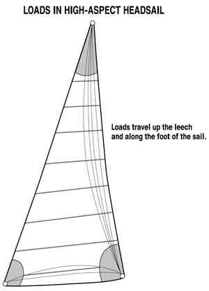 |
| Figure 4.1 When sailing
on the wind, a high-aspect sail like a blade jib will have
the bulk of the load travel almost directly up the leech of
the sail with less stress along the foot. |
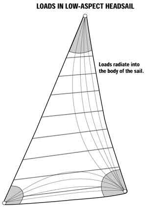 |
| Figure 4.2 A low-aspect
sail will have the loads travel more toward the center of the
sail rather than concentrated along the leech. It will also
experience greater loads along its foot than the high-aspect
sail. |
Note that the loads in a sail are also affected by the
geometry of a rig, and in particular the aspect ratio or
height-to-width ratio of the sail. For example, when sailing on
the wind, a high-aspect sail like a blade jib (Figure 4.1) will
have the bulk of the load travel almost directly up the leech of
the sail with less stress along the foot. A low-aspect sail like
a No. 1 genoa, on the other hand, will have the loads travel more
toward the center of the sail rather than concentrated along the
leech. It will also experience greater loads along its foot than
the high-aspect sail (Figure 4.2) By knowing where the loads fall
and combining this information with the strength and stretch
resistance of the individual yarns, the sail designer can begin
to develop an overall picture of an optimal panel configuration.
As you will see in future chapters the art of aligning yarns
along specific load catenaries has become a sophisticated
process, far more complicated than in the early days when there
were only a few ways to configure a panel layout. As noted in
Chapter 3 many different styles of fabric are available, and a
number of different construction techniques are also available.
Fortunately, it’s not rocket science, and understanding even a
little about how and why sails are built in a particular manner
will go a long way toward helping you make the appropriate
decisions the next time you are in the market for a new sail.
Mitre- and Cross-cut Sails
Before we look at some of the latest sail designs,
however, it’s once again important to look to the past. As was
the case with sail fabrics and yarns, if we understand how we got
to where we are today, we will have some idea of where we might
be going. Sail engineering is all about making good use of raw
materials, both raw fibers and sailcloth.
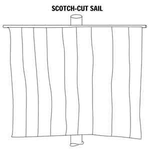 |
| Figure 4.3 Back in the
days of square-riggers and trading schooners all sails were
made with their panels laid parallel to the leech of the
sail in what was referred to as a Scotch-cut pattern. |
 |
| Figure 4.4 The panels meet
in the body of the sail with adjoining panels cut at an angle
to both warp and fill yarns on what was called a heavy bias. |
Back in the days of square-riggers and trading schooners all
sails were made much the same way, i.e., with their panels laid
parallel to the leech of the sail in what was referred to as a
Scotch-cut pattern. This was true for both square sails and
triangular headsails, despite the face that they were subjected
to markedly different forces. (Figure 4.3) Then in the middle of
last century a company by the name of Ratsey and Lapthorn
Sailmakers, based in Cowes on England’s Isle of Wight, realized
that fill yarns had less stretch than their warp counterparts,
and that this fact could be used to some advantage in terms of
sail shape. Specifically, the company discovered that by rotating
the fabric 90 degrees, it was suddenly able to achieve a moderate
amount of leech control, something that had until that point
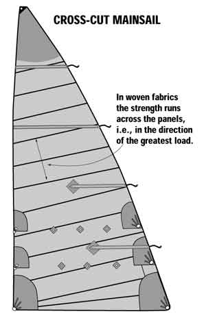
eluded sailmakers. For mainsails, where two out of three edges
are supported by rigid spars, they ran the fabric all the way
across the sail from the leech to the luff in what came to be
called a cross-cut pattern. For the headsails, which were only
supported along the luff by a headstay, they ran the panels
perpendicular to the leech, and perpendicular to the foot as well
so that both parts of the sail would benefit from the
stretch-resistant fill yarns. (Figure 4.4) The panels met in the
body of the sail with adjoining panels cut at an angle to both
the warp and fill yarns on what was called a heavy bias.
Fortunately, the middle of most sails is a low-load area so this
bias didn’t result in too much distortion, although it could be
very difficult to get the sail to look good when there was so
much opportunity for stretch. In the old days, when sailmaking
was more art than science, sailmakers were often judged by how
well they could sight and cut the mitre line.
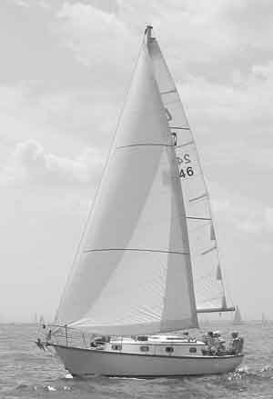 |
| Cross-cut Dacron sails
are the most common sails seen on weekends as small
cruising boats head out for a sail. |
 |
| Figure 4.5 As
sailmakers gained some say in the way fabrics were woven,
they were able to get fill-oriented and balanced fabrics made
that could be used to build increasingly efficient cross-cut
sails, both headsails and mainsails. |
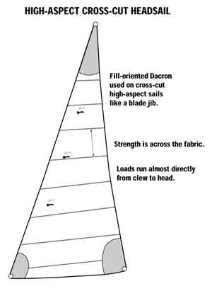 |
| Figure 4.6 Choose a
fill-oriented fabric for a No. 3 blade jib where the loads
run right up the leech of the sail. |
As designs developed and sailmakers gained some say in the way
fabrics were woven, they were able to get fill-oriented and
balanced fabrics made that, depending on the aspect ratio of the
sail, could be used to build increasingly efficient cross-cut
sails, both headsails and mainsails. (Figure 4.5) For example, as
Figure 4.2 shows, a low-aspect sail like a No. 1 genoa of the
kind used on an old IOR racer has the loads fairly evenly
distributed throughout the sail. Therefore, if you had to choose
a single fabric it would likely be a balanced one. If, on the
other hand, you were choosing fabric for a No. 3 blade jib where
the loads run right up the leech of the sail, you would
definitely choose a fill-oriented fabric. (Figure 4.6) As fabrics
became more sophisticated and sailmakers gained a better
understanding of their craft, sail designs improved, and the
demands for better sails increased as well. The quest for light
sails that did not stretch when they came under load remained a
top priority for sail engineers.
A Case for Multiple Plies
The fact that the fabric along the luff of sails was overkill was
not lost on sailmakers, but until they figured out that fabric
could be plied, or made up of multiple layers stacked on top of
one another, there was little they could do about it. Sails were
engineered for the loads on the leech and the excess fabric
strength at the front end (generally in a low load area) got a
free ride. When I worked for Hood Sails in the early 1980s we had
a lock on the maxi-boat market. Maxi boats back then were 80 feet
long, giants for their time, and the sail inventories consisted
of five or six headsails of varying sizes and weights, plus a
number of other sails like trysails and spinnakers. Some of the
boats carried 15 to 20 sails on board each time they left the
dock to go racing, which represented a tremendous bulk. It did
not make any sense to remove excess weight from the boat in the
form of spare tools and unneeded toothbrushes when the bilge was
stuffed with heavy, overbuilt sails. When they were wet, which
was much of the time, it was even more of a problem.
 |
| Figure 4.7 The first
designs had the second ply joining the single ply along an
imaginary line that ran parallel to the leech. |
Crescent-cut and Saw-tooth Sails
Partly out of a desire to save overall weight in the
boat, and partly in an effort to engineer more efficient sails,
sailmakers started to manufacture sails that had a relatively
light base fabric, then added a second ply of woven Dacron along
the high load area, i.e. the leech. This development took place
in the early 1980s and initial forays into two-plied sails, or
sails that had heavier fabric up the leech were not a total
success. The point where the different fabric strengths came
together, for example, was an area that caused problems since a
crease or gutter quickly formed where the seam had to try to
accommodate the contrasting stretch characteristics of the
different fabrics. The first designs simply had the fabrics
joining along an imaginary line that ran parallel to the leech
(Figure 4.7). But as sailmakers began to recognise that there was
more load toward the head and clew, and less in the middle of the
sail, some started to end the second ply in a crescent shape
(Figure 4.8), while others tried their own configurations with
the result that the saw-tooth mainsail (Figure 4.9) and other
aptly named sails became part of sailmaking jargon. In each case,
the basic idea remained the same. Use heavier fabric where it was
needed and keep the rest of the sail light. Another
advantage of these two-ply sails was that they allowed the
designers to combine fabrics in a sail. For example, they could
use a balanced Dacron for the base fabric and a fill-oriented
Dacron for the second ply up the leech. This way the yarns were
being used to their fullest potential. They even tried three-ply
sails, but the added expense of building the sails did not show
commensurate gains in performance. After much analysis and trial
and error, sailmakers found which fabrics could be plied and
matched with others and that if they carried the transition point
further into the body of the sail there was less chance of a
problem occurring. It was a cumbersome process and sail engineers
knew there had to be a better way. Fortunately, it was just about
this same time that laminated fabrics began gaining a foothold in
the industry.
 |
 |
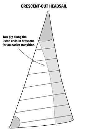
| Figure 4.8 |
Figure 4.9 |
| As sailmakers
began to recognize that there was more load toward the head
and clew, and less in the middle of the sail, some started to
end the second ply in a crescent shape (Figure 4.8), while
others tried their own configurations resulting in the
saw-tooth sail (Figure 4.9). |
A Primer of Panel Layouts will continue in the August 2004 issue
of Northern Breezes.
Brian Hancock is an expert in sails, sailmaking, and offshore
ocean racing, having made a career as a professional sailor for
almost three decades. He apprenticed at Elvstrom Sails in South
Africa before leaving the country to sail around the world. In
1981/82 he sailed as a watch captain aboard the American yacht,
Alaska Eagle in the 27,000 Whitbread Round the World race. Four
years later he returned for a second Whitbread, this time aboard
the British yacht, Drum. In 1989 he sailed as Sailing Master
aboard the Soviet Union’s first, and by happenstance last,
Whitbread entry, Fazisi. With more than 200,000 miles of offshore
sailing to his credit Brian is uniquely qualified to write about
sails and the business of making sails.
Brian also owned
his own boat, Great Circle an Open 50 carbon-fiber,
water-ballasted sailboat designed and built for single-handed
sailing and Brian did a number of solo offshore passages. Some of
his experiences are recounted in his book, The Risk in Being
Alive, published by Nomad Press. These days he works on special
sailing projects and writes for magazines around the world while
raising a family in Marblehead, Massachusetts.
|